

Abstract
The fundamental limits of spatial resolution in positron emission tomography (PET) have been understood for many years. The physical size of the detector element usually plays the dominant role in determining resolution, but the combined contributions from acollinearity, positron range, penetration into the detector ring, and decoding errors in the detector modules often combine to be of similar size. In addition, the sampling geometry and statistical noise further degrade the effective resolution. This paper describes quantitatively describes these effects, discusses potential methods for reducing the magnitude of these effects, and computes the ultimately achievable spatial resolution for clinical and pre-clinical PET cameras.
1. Introduction
There are a relatively small number of physical effects that control the spatial resolution in positron emission tomography (PET) cameras. While most were elucidated in the early days of PET camera development [1, 2], there have been a few changes in the past ~30 years, mainly in the technologies available and the geometries used, and several additional effects have been noted. Therefore, this manuscript summarizes the current understanding of spatial resolution in PET, and also questions whether these effects are truly fundamental. It should be noted that while the dependence of the spatial resolution on the position within the camera is discussed, the magnitude of most effects is usually evaluated at the center of the camera (for calculational simplicity).
2. Physical Effects
2.1 Detector Size
The dominant factor is usually the width of the detector element. Figure 1 (which is not to scale) illustrates the origin and magnitude of this effect, which is due to solid angle coverage and the fact that the position of interaction within the crystal is not determined. The rectangles in Figure 1 represent detector elements (usually scintillator crystals) on opposing sides of the PET detector ring. As a positron-emitting point source is translated from the bottom of Figure 1 to the top, it isotropically emits back-to-back pairs of annihilation photons, and the coincidence rate between the detector pair in question (the darker rectangles) describes a triangle. The rate is zero when the source is below the bottom edge of the detectors, increases roughly linearly from zero at the lower edge of the detector to a maximum when the source is half way between the top and bottom edges, then decreases roughly linearly to zero when the source is at the top edge of the detectors (or goes beyond the top edge). Thus, the response function for this line of response or LOR (the line connecting the two crystals in a detector pair) is a triangle whose full width at half maximum (fwhm) is d/2, where d is the width of the detector element.
Figure 1.

Coincidence response function (coincidence rate versus position) between the two darker detector elements in a PET camera (camera dimensions are not to scale). This function is shown in the middle of the figure, with the y-axis being the position and the x-axis being the coincidence rate.
2.2 Positron Range
The positron is ejected from the nucleus with a few MeV of kinetic energy, so it travels some distance in the subject before it thermalizes and it captures an electron, forming positronium (the bound state of an electron and a positron), which subsequently decays into a pair of 511 keV annihilation photons. Because the position where the annihilation photons are created is different than the position of the parent nucleus, there is some blurring whose magnitude depends of the parent radioisotope species. Table 1 lists the magnitude of this effect for a number of the radioisotopes used for PET [3–6], and the effective blurring ranges from 0.54 mm fwhm for 18F to 6.14 mm fwhm for 82Rb. It should be noted that although the fwhm is quoted, the range distribution is non-Gaussian, with a sharp central cusp with relatively broad tails.
Table 1.
Contribution to spatial resolution due to positron range for several radioisotopes.
| Isotope | Endpoint Energy(MeV) | FWHM(mm) |
|---|---|---|
| F18 | 0.64 | 0.54 |
| C11 | 0.96 | 0.92 |
| N13 | 1.22 | 1.49 |
| O15 | 1.72 | 2.48 |
| Ga68 | 1.90 | 2.83 |
| Rb82 | 3.35 | 6.14 |
2.3 Acollinearity
The positronium has non-zero kinetic energy when it decays, so although the annihilation photons are emitted back-to-back in the positronium rest frame, they are slightly acollinear in the lab frame (with a mean acollinearity angle of 0.2° fwhm) [7]. This angular uncertainty causes a Gaussian blurring that is proportional to the radius of the tomograph detector ring R, and the magnitude of this blurring (in mm fwhm) is given by 0.0044R.
2.4 Decoding
In order to reduce the number of electronics channels, most PET cameras have detectors that employ some form of optical multiplexing, where there are more scintillation crystals than photodetector elements. This decoding is often imperfect, which degrades the spatial resolution. The magnitude of this decoding error has not been studied carefully, but is zero when optical multiplexing (or its equivalent) is not used, and in the early 1990’s was empirically observed to be approximately 2.2 mm fwhm [8]. It is unlikely that this is a “fundamental” value, but instead is tied to the width of the detector element—hardware designers are likely to increase the number of detector elements decoded until errors begin to degrade the ability to identify individual crystals. At the time that the effect was observed to be 2.2 mm, scintillator crystals in PET detector modules were 6–8 mm in cross section, so it is reasonable to quantify this contribution as a Gaussian function of width d/3 fwhm, where d again is the width of the scintillator crystal.
2.5 Penetration
The 511 keV gamma rays often penetrate some distance into the detector ring before they interact and are detected. As shown in Figure 2, if they are not normally incident onto the detector ring, they may interact in a crystal other than the one that they impinge upon, and so get assigned to the “wrong” crystal. The blurring is asymmetric, occurring in the radial direction, and the magnitude of this effect increases as the position of the point source moves radially outward, and so is known as “radial elongation” or “radial astigmatism” [9]. While the quantitative value of the blurring depends on the detector material, the majority of PET cameras are made with either BGO or LSO scintillator, and for these materials, the penetration is described by a Gaussian whose width (in mm fwhm) is given by:
| (Eq. 1) |
Figure 2.

Radial Elongation. Gamma rays emanating from the source penetrate into the detector ring before they interact and are detected. Those impinging normally to the detector ring (travelling horizontallyin this figure) interact in the same crystal, independent of penetration depth, so the tangential projection of the source remains narrow. Those impinging at an oblique angle (travelling vertically in this figure) can interact several different crystals, depending on penetration depth, so the radial projection of the source becomes wide.
2.6 Sampling Error
The final effect that degrades spatial resolution is the sampling error. The fundamental measurement in PET is the number of coincident events recorded by a detector-detector pair, known as a chord or a line of response (LOR). Figure 3 shows all of the lines of response in a (circular) PET camera, and it is clear that the sampling in the camera field of view is not uniform—some pixels in the field of view have a large number of LORs going through them and some are transected by very few lines of response. The effect is especially pronounced near the center of the camera. The fact that these lines of response are spaced uniformly (separated by the crystal width d) creates a degradation factor that has been empirically observed to multiply all the other contributions by a factor of 1.25 [9].
Figure 3.

Sampling Error. The lines of response (lines connecting all detector–detector pairs). The dark spots at the perimeter are the locations of the 24 crystals. The sampling depends strongly on the position in the field of view, especially near the center. While the pixel at the exact center is very well sampled (has many LORs going through it), nearby pixels are very poorly sampled (only a few LORs go through them).
2.7 Total Spatial Resolution
Although some of the response functions are not well-described by a Gaussian function (notably the detector response and the positron range), it is generally assumed that all the effects above add in quadrature, implying that the intrinsic reconstructed spatial resolution Γ for a point source located at a radius r from the center of the camera ring is given by:
| (Eq. 2) |
where d is the crystal width, s is the positron range, b is the crystal decoding error factor (d/3 for detector designs that utilize optical decoding, zero otherwise), and R is the detector ring radius. The factors in the quadrature sum in Eq. 2, going from left to right, are due to the detector size, the positron range, acollinearity, decoding error, and penetration, and the multiplicative factor of 1.25 is due to the reconstruction algorithm. These effects are shown diagrammatically in Figure 4.
Figure 4.

Contributions to Spatial Resolution. This figure shows diagramatically the contributions to spatial resolution in PET.
2.8 Additional Considerations
Eq. 2 holds for a point source when there are a large number of counts in the image. In clinical imaging situations, the finite number of detected events adds statistical noise (which is amplified by the reconstruction algorithm), and so some form of spatial smoothing or averaging is usually performed. There is no simple metric for estimating the amount that statistical noise degrades the resolution, as the raw noise depends on the number of counts and the amplification factor depends their distribution in the object. However, the amplification factor gets larger as the number of voxels containing activity increases, so an accurate measurement of the point spread function (the image of a point source) can be made with as few as tens of thousand events per imaging plane, whereas a typical image in a patient (where there are a large number of voxels containing activity) requires millions of events per imaging plane to achieve similar image quality. Figure 5 shows an example of this, using PET images taken with the same camera and reconstructed to have the same spatial resolution. Figure 5a is the image of an object where the activity is concentrated into a few pixels, and was made with 100,000 events. Figure 5b is the image of a more clinical object where the activity is distributed over many pixels, and has considerably more noise, even though it has ten times the number of events as Figure 5a. Figure 5c shows the same object as shown in Figure 5b, but with 55 times the number of events, and so achieves similar resolution and noise as the object in Figure 5a. Many take advantage of this property by using 18F-fluoride for demonstrating spatial resolution in vivo—it has very high accumulation in bone and low accumulation in the rest of the tissues, so there is significant activity in only a small fraction of the subject’s volume.
Figure 5.
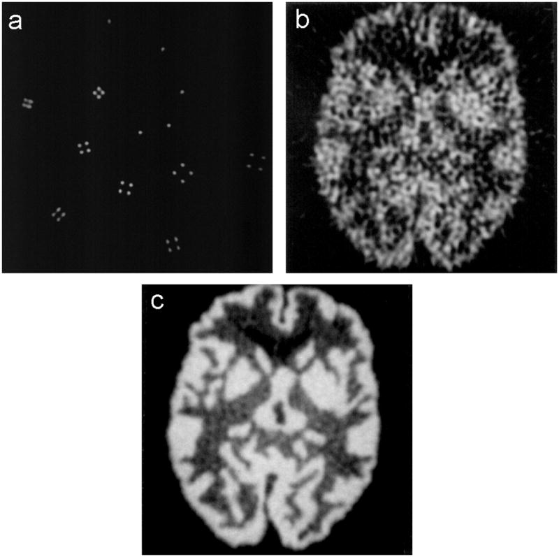
Three PET images taken with the same PET camera and reconstructed with the same spatial resolution. a) an object with activity in a small number of voxels, taken with 100,000 events. b) an object with activity in a large number of voxels, taken with 1,000,000 events. c) the same object as in b), but taken with 55,000,000 events.
The reconstructed spatial resolution also depends on the reconstruction algorithm used. It traditionally has been measured using images reconstructed with the filtered backprojection algorithm with a sharp (Ra-La) filter. More recently, statistical reconstruction algorithms have effectively supplanted filtered backprojection, but care must be used when using them to evaluate spatial resolution. Statistical algorithms have a “positivity constraint” that prohibits voxels from having negative activity. The source distribution commonly imaged to determine spatial resolution is a point source with no background activity. While statistical noise creates a background consisting of voxels with small amounts of activity fluctuating around zero when using filtered backprojection, the positivity constraint eliminates the possibility of negative values when statistical reconstruction algorithms are used, and as the total activity in the background regions should average zero, voxels with positive values are effectively eliminated. This artificially distorts the image by forcing all the activity into the voxels containing the source. This problem is often addressed by having the background regions have a “warm” (non-zero) level of activity away from the point source, which allows both positive and negative fluctuations in the background.
3. Changing the “Fundamental” Limits
Although the individual terms in Eq. 2 represent the physical factors that limit spatial resolution in PET and Eq. 2 accurately describes the spatial resolution in PET cameras, one can still question whether it represents the “fundamental” limits of spatial resolution—are these limits truly fundamental? Therefore, this section investigates whether it is possible to reduce the magnitude of the individual physical effects, or possibly even eliminate them.
3.1 Detector Size
The fundamental limit on the width of the detector element is probably set by the distance in the detector traveled by the photoelectron (or Compton electron) created by the initial gamma ray interaction, which is <50 μm. In practice, this limit is set by practical considerations. Current clinical PET cameras have ~30,000 scintillator crystals, each roughly 4×4×20 mm3. Reducing the crystal width by an order of magnitude (to 0.4 mm) would increase the number of individual crystals that must be cut and assembled to ~3 million, and the number of electronics channels is likely to increase by a similar factor. With 0.4 mm wide crystals, the width of reflector coating the scintillator crystal (typically ~0.1 mm) may represent a significant fraction of the volume of the crystal array, reducing detection efficiency. While some potential solutions exist (detector modules with scintillator crystal arrays having 0.5 mm or better pitch have been fabricated [10], and volumetric solid-state detectors can achieve intrinsic spatial resolutions of ~0.125 mm [11]), the most common approach is to determine the combined magnitude of the other resolution-degrading effects, then choose a detector element size so that its contribution to the spatial resolution is similar to the combined contributions of the other effects.
3.2 Positron Range
The positron endpoint energy is truly a fundamental property of the racer isotope, and so cannot be changed other than by using a different isotope (which is usually impractical, as the isotope is determined by the radiotracer compound). For a given energy, the range depends on the density of the material the positron travels through (i.e., the tissue), but given that one wishes to image humans and animals in physiological conditions, that density cannot be altered. Placing the subject in a strong magnetic field (several Tesla) will cause the positron to travel in helical path, which will reduce the distance between the positron’s emission and annihilation point, especially in the plane transverse to the magnetic field. While this has been demonstrated [12], the costs of such a magnet and of creating a PET camera that can operate in this magnet are significant. However, there is a growing interest in dual-modality PET-MRI scanners [13], which necessarily incorporate such magnets, so these systems are expected to have a decreased contribution from positron range. Attempts have also been made to deconvolve the positron range in the reconstruction algorithm, and while this has been demonstrated [14], it amplifies the statistical noise and so is only useful in the limit of an infinite number of events. Given that the effects of positron range can at best be reduced, and then at significant cost, it should probably be considered a fundamental limitation.
3.3 Acollinearity
The acollinearity angle is set by the amount of kinetic energy that the positronium has when it decays, which is set by the energy that the positron has when it thermalizes, which is set by the temperature of the subject’s tissue. The acollinearity contribution can be reduced by a factor of 1.5 by cooling to −4° C, and by a factor of 5 by cooling to −144° C [7]. While this represents a substantial improvement, it is not a practical solution, as cooling to these temperatures is quite likely to change the physiologic properties that we are trying to probe! Thus, acollinearity must be considered a fundamental limitation.
3.4 Decoding
As described earlier, the decoding error can be zero, especially if no multiplexing is used. This is possible and PET cameras that do not employ decoding (e.g., one photodetector per scintillator crystal) have been constructed. The drawback is generally the increased number of photodetectors, electronics channels, and construction complexity, which ultimately imply an increased cost. However, the contribution due to decoding error should not be considered to be fundamental.
3.5 Penetration
Radial elongation is caused by the gamma ray penetrating into the detector ring coupled with the fact that the detector module does not determine the interaction point, but the interaction crystal. If a volumetric detector module (one that measures the 3-D interaction position, as opposed to two dimensions of this position) were used, then the LOR would be correctly defined by the two interaction points, eliminating this source of blurring. Although they are not common, several PET cameras with the ability to measure the depth of interaction (in addition to the crystal of interaction) have been constructed and the reduction/elimination of this blurring factor has been confirmed [15]. In general, the drawback of this approach is complexity and/or cost.
An alternate approach is to model this penetration and correct for it in the reconstruction algorithm. While this has been demonstrated, it has the drawback of amplifying the statistical noise, and so is most effective when there are a large number of counts [16]. Thus, from a strictly performance standpoint, measuring the depth of interaction (which corrects for penetration on an event by event basis) is preferable to deconvolving the penetration (which corrects on a statistical basis). However, the deconvolution can be done with existing cameras (and so is much easier to implement) and has been shown to produce noticeable improvements with a reasonable number of events [17]. Thus, the degradation caused by penetration is not fundamental.
3.6 Sampling Error
The origin of the sampling error is that parallel chords are spaced a distance d apart, where d is the detector width. There are several methods that can reduce this sampling distance and so reduce the sampling error. A brute-force method that was used in 1980’s was to physically move the camera around the subject, most commonly in a circular motion with a diameter of d (known as “wobble” [9]) but occasionally other forms of motion (such as the “clamshell” motion [9]) were used. Alternatively, the subject can be moved with this motion.
Another way of eliminating the sampling error is by using different detector technologies. While detectors that have depth of interaction measurement do not automatically improve the sampling, virtually all camera geometries that incorporate depth of interaction measurement have considerably more lines of response than the conventional circular ring geometry, thereby increasing the sampling density. In addition, detectors that measure the interaction position as a continuous number (e.g., by taking the ratio of two signals) can have LORs that are spaced arbitrarily closely together, and so eliminate the sampling error. Thus, the sampling error is not fundamental.
3.7 Ultimate Spatial Resolution
How small can we reasonably make each factor, and hence the spatial resolution of a clinical or pre-clinical PET camera? The decoding error factor b is 0 mm for detectors that do not use light sharing to decode crystals. The term due to penetration can be eliminated using a design that measures depth of interaction, which has the additional benefit of reducing the multiplicative factor from the sampling from 1.25 to 1.0. The positron range s is isotope dependent, but the minimum among the common positron emitting isotopes is 0.5 mm for 18F. The acollinearity factor 0.0044R can be made arbitrarily small by reducing R, but the ring must be large enough to accommodate the subject being imaged. This is roughly 400 mm radius for clinical cameras and 10 mm radius for pre-clinical (small animal) cameras. Thus, the spatial resolution Γ for this “ultimate” design is given by:
| (Eq. 3) |
where d is the crystal width, s is the positron range, and R is the detector ring radius.
Only the positron range and acollinearity factors cannot be reduced, and they combine to be 0.67 mm fwhm for pre-clinical PET cameras and 1.83 mm fwhm for clinical PET cameras. This is the spatial resolution that would be achieved with zero width detector elements, and represents the fundamental limit of PET camera spatial resolution. Zero width detector elements are impractical, and it makes little sense to construct a camera with crystal width smaller than the fundamental resolution limit—such cameras would have spatial resolution that is only 12% larger than a camera with zero width detector elements (0.75 mm fwhm for pre-clinical and 2.05 mm for clinical PET cameras). Using detector widths that represent a reasonable compromise between spatial resolution and practical manufacturing considerations (1.0 mm for pre-clinical PET, 3.0 mm for clinical PET), pre-clinical PET and clinical PET cameras can achieve 0.83 mm fwhm and 2.36 mm fwhm reconstructed spatial resolution respectively, but these cameras must use detector designs that measure depth of interaction and do not have decoding error.
4. Conclusions
The “fundamental” effects that limit the spatial resolution in PET cameras are the detector width, the positron range, and the acollinearity. Additional effects that degrade spatial resolution in most PET cameras, but can be reduced or eliminated through careful camera design, are decoding error, penetration into the detector ring, and sampling. The fundamental limit for clinical and pre-clinical PET cameras is 1.83 mm fwhm and 0.67 mm fwhm respectively, and practical PET cameras can be made with resolutions of 2.36 mm fwhm and 0.83 mm fwhm for clinical and pre-clinical PET cameras respectively.
Acknowledgments
I would like to thank Drs. Stephen E. Derenzo, Ronald H. Huesman, and Thomas F. Budinger of Lawrence Berkeley National Laboratory for the many useful discussions that I have had with them, and which have provided virtually all of my understanding of PET. This work is supported in part by the Director, Office of Science, Office of Biological and Environmental Research, Medical Science Division of the U.S. Department of Energy under Contract No. DE-AC02-05CH11231, and in part by the National Institutes of Health, National Institute of Biomedical Imaging and Bioengineering under grants No. R01-EB006085 and R21-EB007081.
Footnotes
Publisher's Disclaimer: This is a PDF file of an unedited manuscript that has been accepted for publication. As a service to our customers we are providing this early version of the manuscript. The manuscript will undergo copyediting, typesetting, and review of the resulting proof before it is published in its final citable form. Please note that during the production process errors may be discovered which could affect the content, and all legal disclaimers that apply to the journal pertain.
References
- 1.Muehllehner G. Resolution limit of positron cameras. J Nucl Med. 1976;17:757. [PubMed] [Google Scholar]
- 2.Derenzo SE, Budinger TF, Cahoon JL. High resolution computed tomography of positron emitters. IEEE Trans Nucl Sci. 1977;NS-24:544–558. [Google Scholar]
- 3.Cho ZH, Chan JK, Ericksson L, Singh M, Graham S, et al. Positron ranges obtained from bimedically important positron-emitting radionuclides. J Nucl Med. 1975;16:1174–1176. [PubMed] [Google Scholar]
- 4.Derenzo SE. Precision measurement of annihilation point spread distributions for medically important positron emitters. In: Hasiguti RR, Fujiwara K, editors. Proceedings of The Positron Annihilation. Sendai, Japan: 1979. pp. 819–823. [Google Scholar]
- 5.Derenzo SE, Budinger TF, Huesman RH, Cahoon JL. Dynamic positron-emission tomography in man using small bismuth germanate crystals. Proceedings of The Sixth International Conference on Positron Annihilation; Ft. Worth, TX. 1982. pp. 1–11. [Google Scholar]
- 6.Levin CS, Hoffman EJ. Calculation of positron range and its effect on the fundamental limit of positron emission tomography system spatial resolution. Phys Med Biol. 1999;44:781–799. doi: 10.1088/0031-9155/44/3/019. [DOI] [PubMed] [Google Scholar]
- 7.Colombino P, Fiscella B, Trossi L. Study of positronium in water and ice from 22 to −144 °C. Nuovo Cimento. 1965;38:707–723. [Google Scholar]
- 8.Moses WW, Derenzo SE. Empirical observation of performance degradation in positron emission tomographs utilizing block detectors. J Nucl Med. 1993;34:101P. [Google Scholar]
- 9.Derenzo SE, Budinger TF, Huesman RH, Cahoon JL, Vuletich T. Imaging properties of a positron tomograph with 280 BGO crystals. IEEE Trans Nucl Sci. 1981;NS-28:81–89. [Google Scholar]
- 10.St James S, Yang Y, Wu Y, Farrell R, Dokhale P, et al. Experimental characterization and system simulations of depth of interaction PET detectors using 0.5 mm and 0.7 mm LSO arrays. Phys Med Biol. 2009;54:4605–4619. doi: 10.1088/0031-9155/54/14/015. [DOI] [PMC free article] [PubMed] [Google Scholar]
- 11.Yin Y, Komarov S, Wu H, Song TY, Li Q, et al. Characterization of highly pixelated CZT detectors for sub-millimeter PET imaging. In: Yu B, editor. Proceedings of The IEEE 2009 Nuclear Science Symposium and Medical Imaging Conference. Orlando, FL: 2009. pp. 2411–2414. [Google Scholar]
- 12.Raylman RR, Hammer BE, Christensen NL. Resolution due the effects of a static homogeneous magnetic field. IEEE Trans Nucl Sci. 1996;NS-43:2406–2412. [Google Scholar]
- 13.Pichler B, Judenhofer M, Wehrl H. PET/MRI hybrid imaging: devices and initial results. European Radiology. 2008:1077–1086. doi: 10.1007/s00330-008-0857-5. [DOI] [PubMed] [Google Scholar]
- 14.Haber SF, Derenzo SE, Uber D. Application of mathematical removal of positron range blurring in positron emission tomography. IEEE Trans Nucl Sci. 1990;NS-37:1293–1299. [Google Scholar]
- 15.de Jong HWAM, van Velden FHP, Kloet RW, Buijs FL, Boellaard R, et al. Performance evaluation of the ECAT HRRT: an LSO-LYSO double layer high resolution, high sensitivity scanner. Phys Med Biol. 2007;52:1505–1526. doi: 10.1088/0031-9155/52/5/019. [DOI] [PubMed] [Google Scholar]
- 16.Huesman RH, Salmeron EM, Baker JR. Compensation for crystal penetration in high resolution positron tomography. IEEE Trans Nucl Sci. 1989;NS-36:1100–1107. [Google Scholar]
- 17.Alessio AM, Kinahan PE, Lewellen TK. Modeling and incorporation of system response functions in 3-D whole body PET. IEEE Trans Med Img. 2006;25:828–837. doi: 10.1109/tmi.2006.873222. [DOI] [PubMed] [Google Scholar]