Figure 5.
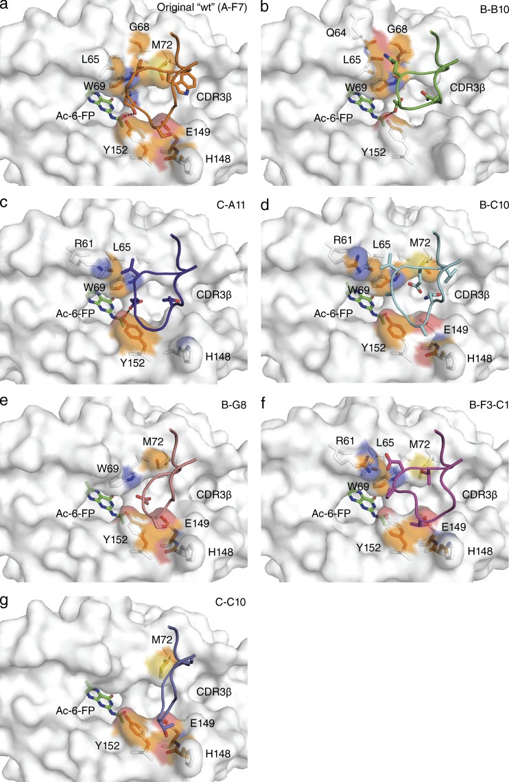
Differential CDR3β usage and MAIT TCR-MR1-Ag recognition. Structural representation of the MR1 surface in white with Ac-6-FP bound, shown in green. MAIT TCR CDR3β loops for the 7 structures are indicated for (a) original WT (TRBV6-1, clone A-F7) in orange, (b) B-B10 in green, (c) C-A11 in purple, (d) B-C10 in cyan, (e) B-G8 in salmon, (f) B-F3-C1 in magenta, and (g) C-C10 in slate. Contacting residues between MR1 and the CDR3β loops are shown in stick representation with the contact surface on MR1 shown according to the MR1 element type: carbon, orange; nitrogen, blue; oxygen, red; and sulfur, yellow. CDR boundaries are listed in Table 1.

