

Abstract
We report here the fabrication of three dimensional (3D) interconnected macro porous tricalcium phosphate (TCP) scaffolds with controlled internal architecture by direct 3D printing (3DP), and high mechanical strength by microwave sintering. TCP scaffolds with 27%, 35% and 41% designed macro porosity having pore sizes of 500 μm, 750 μm, and 1000 μm, respectively, have been fabricated via direct 3DP. These scaffolds are then sintered at 1150 °C and 1250 °C in conventional electric muffle furnace as well as microwave furnace. Total open porosity between 42% and 63% is obtained in the sintered scaffolds due to the presence of intrinsic micro pores along with the designed pores. A significant increase in compressive strength, between 46% and 69%, is achieved by microwave sintering as compared to conventional sintering as a result of efficient densification. A maximum compressive strength of 10.95 ± 1.28 MPa and 6.62 ± 0.67 MPa is achieved for scaffolds with 500 μm designed pores (~400 μm after sintering) sintered in microwave and conventional furnaces, respectively. An increase in cell density with a decrease in macro pore size is observed during in vitro cell-material interactions using human osteoblast cells. Histomorphological analysis reveals that the presence of both micro and macro pores facilitated osteoid like new bone formation when tested in the femoral defect on Sprague-Dawley rats. Our results show that bioresorbable 3D printed TCP scaffolds have great potential in tissue engineering applications for bone tissue repair and regeneration.
Keywords: Tricalcium phosphate, 3D printing, microwave sintering, macro porous, interconnected pores, compressive strength, in vivo, osteogenesis
1. Introduction
The increasing need for skeletal reconstruction due to bone tumors, trauma, disease, birth defects, and/or war injury demands improved biological and mechanical properties of the existing scaffold materials. Calcium phosphate (CaP) bioceramics are widely used in bone-tissue engineering due to their excellent bioactivity, osteoconductivity and compositional similarities to bone (Bandyopadhyay et al., 2006; Banerjee et al., 2010). CaPs offer the advantage of being custom manufactured with respect to the patient and target application based on the CT scan of the defect site (Hollister, 2005). Among other CaPs, tricalcium phosphate (TCP) is one of the most widely used materials due to its bioresorbable property. The bioresorbability of TCP helps it to degrade over time with the ingrowth of host tissues and makes it suitable for many applications.
It is widely accepted that internal architecture of scaffolds has an important role to play in tissue engineering applications, along with mechanical and biological properties. The presence of highly interconnected three dimensional (3D) pores in the scaffolds are beneficial to promote cell adhesion, mechanical interlocking between host tissue and scaffold via bone ingrowth, and transport of nutrients and metabolic waste (Ramay and Zhang, 2004; Yang et al., 2002; Sicchieri et al., 2011). On the other hand, scaffolds must also have sufficient strength to withstand in vivo stresses at the site of application until newly formed bone replaces the biodegradable scaffold matrix via new bone regeneration (Hutmacher, 2000).
It is known that porosity characteristics such as pore size, volume fraction, percent porosity and pore shape have strong influence on mechanical properties of ceramics (Groot, 1988; Bose et al., 2003; Hattiangadi and Bandyopadhyay, 2004). The ability to create scaffolds with designed 3D interconnected porosity can elicit specific, desired, and timely responses to induce early stage osteogenesis from the surrounding cells and tissues through cell migration, tissue ingrowth and nutrient transportation into interconnected macro pores (Will et al., 2008). However, fabrication of CaP scaffolds with complex geometrical features is difficult by conventional manufacturing techniques as pore size, pore distribution, pore interconnectivity and percent porosity cannot be precisely controlled (Sachlos and Czernuszka, 2003; Butscher et al., 2011). Solid freeform fabrication (SFF) techniques allow flexibility in designing and manufacturing scaffolds with complex geometry (Hollister, 2005; Sun et al., 2004). Among many existing SFF methods, fused deposition modeling (FDM), selective laser sintering (SLS), stereolithography (SLA), and three dimensional printing (3DP) are most widely used methods to fabricate porous bio-ceramic scaffolds (Hollister, 2005). Either hydroxyapatite (HA) (Will et al., 2008) or β-tricalcium phosphate (β-TCP) (Khalyfa et al., 2007) alone or a mixture of these two, such as biphasic CaP (Ramay and Zhang, 2004), in some cases with polymer (Taboas et al., 2003), have been used to fabricate porous scaffolds for tissue engineering applications. Although SFF methods allow great flexibility to fabricate scaffolds with complex architecture, in most cases, scaffolds suffer from having poor mechanical properties (Khalyfa et al., 2007).
The most critical factor for a scaffold is to provide adequate mechanical support for bone tissue ingrowth. Microwave sintering of ceramics to achieve improved mechanical properties has widely been used by the scientific community. Heating mechanism makes microwave sintering different than the conventional sintering. In conventional sintering, heat dissipates into a material from outside to inside through radiation, conduction and convection; this requires longer sintering time resulting in undesired grain growth (Yadoji et al., 2003). As a result, conventional sintering is termed as surface heating, and is dependent on the rate of heat flow into the material. Unlike the thermal heat flux in conventional sintering; materials absorb microwave energy in the form of electro-magnetic radiation in microwave sintering, and transform this energy into heat within the sample volume (Yadoji et al., 2003). This leads to improved heating uniformity and shorter sintering time by microwave sintering than conventional sintering, which results in controlled grain growth, and better densification without significant crack development. Controlled grain growth, and higher densification lead to improved mechanical properties of sintered ceramics than those sintered by conventional sintering. Thus, significant advantages of microwave sintering over conventional sintering are rapid volumetric heating rate, improved reaction, shorter processing time due to enhanced sintering rate, and cost effectiveness in terms of energy savings (Yadoji et al., 2003; Chanda et al., 2009; Bose et al., 2010).
The purpose of this study was to fabricate TCP scaffolds with controlled interconnected macro pores using 3DP technology, and to achieve improved mechanical strength using microwave sintering. Once fabricated, the scaffolds were sintered using two different sintering methods, conventional heating using a muffle furnace, and microwave heating. The 3D printed TCP scaffolds had three different interconnected pore sizes. The influence of porosity and pore sizes on mechanical strength, in vitro bone cell-material interactions, and in vivo osteogenesis were studied. In vitro cell-material interactions were investigated using human osteoblast cells. Effects of micropores, and interconnected macropores on early stage osteogenesis were evaluated in vivo by implanting scaffolds in the femoral defect of male Sprague-Dawley rats for 2 weeks.
2. Materials and methods
2.1. Scaffold fabrication and characterization
Commercially available β-TCP powder with an average particle size of 550 nm was used (Berkeley Advanced Biomaterials Inc., Berkeley, CA). Cylindrical scaffolds of 7 mm diameter and 10.5 mm height with three different 3D interconnected square shaped macro pore sizes were designed for mechanical strength comparison. Square shaped designed macro pores were 500 μm, 750 μm and 1000 μm, respectively, penetrating orthogonally through the cylindrical shape in X, Y, and Z directions. These designed scaffolds were fabricated using a 3D printer (ProMetal®, ExOne LLC, Irwin, PA, USA), a technology originally developed at MIT (Sachs et al., 1990). A schematic of 3DP is shown in Figure 1. The process begins with laying a thin layer of powder bed in the build box. A roller spreads the powder from feed bed onto the build bed. The print head moves across the loose powder bed selectively printing the liquid binder (aqueous based binder, purchased from ProMetal®, ExOne LLC, Irwin, PA, USA) based on CAD model cross-sectional area of the designed part. The powder bed with printed binder moves under a heater plate to expel the moisture and to limit binder spreading between the layers. The powder outside the part geometry remains loose and act as support for subsequent layers. The build platform then moves down by one layer thickness, typically 20 μm, and then the roller spreads a new layer of powder on top of the previous layer. The print head applies the binder based on the part geometry as before. This process continues by repeating these steps to complete the part printing. Some very important optimized 3D printing process parameters used for TCP scaffold fabrication are presented in Table 1 along with their significance.
Figure 1.

Schematic of 3D printing.
Table 1.
Some important optimized 3D printing process parameters for TCP scaffolds fabrication using aqueous based binder (ProMetal®, ExOne LLC, Irwin, PA, USA), and 550 nm particle size β-TCP powder (Berkeley Advanced Biomaterials Inc., Berkeley, CA)
| Parameters | Optimized Values |
Significance |
|---|---|---|
| Layer thickness | 20 μm | This might vary depending on the complexity of the part geometry and powder morphology. A thinner layer allows the binder bleed through outside the part design. A thicker layer requires high desired saturation. Using a high saturation also leads to same problem. This binder bleeding causes blocking of any designed pores. |
| Feed powder to layer thickness ratio | 3 | A feed powder to layer thickness ratio greater than 2 is necessary. A high ratio ensures enough powder supply during spreading to get an evenly spread layer. |
| Foundation layers | 6 | This parameter has more freedom to start with, and has less direct impact on other parameters. |
| Drying power Control setting | 35 % | This controls the heating temperature of the heater. A high heating dries up the binder before it gets the chance to join the particles in the designated design area, while a low heating end up with residual binder on top of the layer. This residual binder does not get enough time to dry up before the next spread, and leads to part deterioration. |
| Drop volume | 119.5 pL | This is the amount of binder released from the individual nozzle of the print head, and depends on the binder density. This gives an idea about desired saturation. |
| Desired saturation | 110 % | This parameter depends on the drop volume. A high measure of the drop volume requires a low desired saturation and vice versa. Desired saturation might vary by the layer thickness, and powder morphology. A thicker layer would require relatively high saturation. |
| Computed saturation | 110 % | Desired saturation is communicated to the machine through computed saturation. Computed saturation needs to be set equal to desired saturation before printing is started. |
| Roller spread speed | 0.5 mm/sec | This also depends on the powder morphology, and is very important for uniform spreading. Finer particles require a relatively slower spread speed, whereas relatively higher spread speed could be set for coarse particles. |
After 3D printing, the binder was allowed to harden at 175°C for 90 min to form a green ceramic body. The loosely adhering powder in the pores was removed via dry ultrasonication and/or air blowing. To study the influence of sintering method on mechanical properties, green scaffolds were sintered at 1150°C and 1250°C in a conventional muffle furnace for 2 h (sintering cycles: heating rate 3°/min up to 120 °C, dwell time at 120 °C: 1h; then heating rate 3°/min up to 600 °C, dwell time at 600 °C: 1h, then heating rate 1°/min up to 1150 °C or 1250 °C, dwell time: 2h, cooling rate: 10°/min), and in a 2.45 GHz 3 KW microwave furnace (MW-L0316V, LongTech Co., Ltd, ChangSha, HuNan, P. R. China) for 1 h. Phase analysis of sintered β-TCP scaffolds was carried out by X-ray diffraction (XRD) using a Philips PW 3040/00 Xpert MPD system (Philips, Eindhoven, The Netherlands) with Cu Kα radiation and a Ni filter. Samples were scanned over a 2θ range of 20° to 60° at a step size of 0.02° and a count time of 0.5 s per step. Phase percentage of α-TCP and β-TCP in the sintered scaffolds was determined from the relative intensity ratio of the corresponding major phases using the following relationship (Pattanayak et al., 2007):
Apparent densities of sintered scaffolds were determined by the Archimedes’ principle, which accounts for the closed porosity within the scaffold walls. Bulk densities of the sintered scaffolds were determined using mass and physical dimensions of the scaffolds. The bulk density accounts for both the closed and the open porosities in the scaffolds. The total open porosities of the scaffolds were measured from the apparent and the bulk densities.
Images for microstructure and pore size measurement after sintering were taken using field-emission scanning electron microscope (FESEM) (FEI Inc., Hillsboro, OR, USA). Sintered pore size was measured and averaged from 3 samples for each pore size taking 3 different pores from each sample. Compressive strength of sintered scaffolds was determined using a screw-driven universal testing machine (AG-IS, Shimadzu, Tokyo, Japan) with a constant cross-head speed of 0.33 mm min−1. Compressive strength was calculated using the maximum load at failure and initial sample dimensions. For compressive strength analysis, 10 samples (n = 10) from each pore size at each sintering temperature were used.
2.2. In vitro cell material interactions
In vitro bone cell materials interactions on sintered scaffolds were investigated using human fetal osteoblast cells (hFOB) for 3, 7 and 11 days of incubation period. Cells used in this study were immortalized osteoblastic cell line, which was derived from human bone tissue. All samples were sterilized by autoclaving at 121°C for 30 min prior to cell culture. Aliquot of 150 μL cell suspension containing 2 × 10⁵ cells were seeded by unidirectional seeding directly on each samples placed in the wells of 24-well plates. After cell seeding, a 1 mL aliquot of DMEM media enriched with 10% fetal bovine serum was added to the surrounding of each sample in the well. Cultures were maintained at 37 °C under 5 % CO2 / 95 % humidified air atmosphere. The culture media was changed every alternate day for the duration of the experiment.
2.2.1. Cell morphology
Cell morphology was assessed by SEM observation. All samples for SEM observation were fixed with 2% paraformaldehyde/2% glutaraldehyde in 0.1 M cacodylate buffer overnight at 4 °C. Post fixation for each sample was performed with 2% osmium tetroxide (OsO4) for 2 h at room temperature. Fixed samples were then dehydrated in an ethanol series (three times for each of 30%, 50%, 70%, 95%, and 100%), followed by a hexamethyldisilane (HMDS) drying procedure. Dried samples were then gold coated (Technics Hummer V, San Jose, CA, USA), and observed under an FESEM, equipped with an ETD (Everhart-Thornley Detector), in high vacuum at 30 kV acceleration voltage.
2.2.2. Cell proliferation using MTT assay
The MTT assay (Sigma, ST. Louis, MO) was performed for 3, 7 and 11 days of incubation to assess hFOB cell proliferation on 3D interconnected macro porous β-TCP scaffolds. The MTT solution of 5 mg mL−1 was prepared by dissolving MTT in PBS, and filter sterilized. The MTT was diluted (50 μL into 450 μL) in serum free, phenol-red free Dulbecco’s Minimum Essential (DME) medium. 100 μL diluted MTT solution was then added to each sample in 24-well plates. After 2 h of incubation, samples were taken into new well plate and 1 mL solubilizer (made up of 10% Triton X-100, 0.1 N HCl, and isopropanol) was added to each well to dissolve the formazen crystal. 100 μL of the resulting supernatant was transferred into a 96-well plate, and read by a plate reader at 570 nm. Triplicate samples per group were evaluated and three points were measured from each sample.
2.3. In vivo osteogenesis
In vitro cell-materials interactions on present β-TCP scaffolds showed significant increase in cell adhesion, growth and proliferation on scaffolds with the smallest pore size i.e., 500 μm of designed pores. Therefore, for in vivo study, implants of 3.4 mm diameter and 5.2 mm height with 230 μm, 350 μm, and 470 μm interconnected designed macro pores were designed and fabricated. All scaffolds for in vivo study were microwave sintered at 1250 °C for 1 h and then sterilized as described earlier.
2.3.1. Surgery and implantation procedure
Sprague-Dawley rats between 280 to 320 grams (Charles Rivers Laboratories International, Inc., Wilmington, MA, USA) were used in this study. Surgeries were performed according to the protocol approved by the Institutional Animal Care and Use Committee (IACUC), Washington State University. Prior to surgery, the rats were housed in individual cages with alternating 12 h cycles of light and dark in temperature and humidity controlled rooms. Following acclimatization, all animals underwent a surgery to create femoral defect. Rats were anesthetized using IsoFlo® (isoflurane, USP, Abbott Laboratories, North Chicago, IL, USA) coupled with an oxygen (Oxygen USP, A-L Compressed Gases Inc., Spokane, WA, USA) regulator, and monitored by pedal reflex and respiration rate to maintain proper surgical anesthesia. The defect was created in the distal femur by means of a drill bit between 2 and 3 mm diameter. The cavity was rinsed with physiological saline to wash away remaining bone fragments. Following implantation, undyed braided-coated polyglycolic acid synthetic absorbable surgical suture (Surgical Specialties Corporation, Reading, PA, USA) was used for stitching. Disinfectant was applied to the wound site to prevent infection. At 2 and 4 weeks post-surgery, rats were euthanized by overdosing with halothane in a bell jar, followed by administration of a lethal injection of potassium chloride (70%) into the heart.
2.3.2. Histomorphology
The bone-implant specimens were fixed in 10% buffered formalin solution and dehydrated in graduated ethanol (70%, 95%, and 100%), ethanol-acetone (1:1), and 100% acetone series. After embedding samples in Spurr’s resin, each undecalcified implant block was sectioned perpendicular to implant axis using a slow speed diamond wheel. After polishing, the sections were stained by Masson Goldner’s trichrome stain and observed under a light microscope [Olympus BH-2, Olympus America Inc., USA].
2.4. Statistical analysis
Data for volume fraction porosity, pore size, shrinkage, compressive strength, and MTT assay is presented as mean ± standard deviation. Statistical analysis was performed on compressive strength and MTT assay results using student’s t-test, and P value < 0.05 was considered significant.
3. Results
3.1. Porosity, phase, microstructure and mechanical properties
Typical microwave sintered β-TCP scaffolds fabricated using 3DP are shown in Figure 2 (a). All sample showed clear interconnected macro porosity across the sample. Table 2 shows pore size and percent shrinkage of the scaffolds sintered in conventional electric furnace at 1250°C for 2 h and microwave furnace at 1250°C for 1 h. Conventionally sintered scaffolds showed relatively low shrinkage between 11 and 18% compared to microwave sintered scaffolds which exhibited shrinkages between 19 and 26%. All scaffolds showed more shrinkage in radial direction than in longitudinal direction, which resulted in smaller pore size in radial direction. Table 3 compares designed porosity with experimentally determined total open porosity of the scaffolds sintered at different temperatures and times. Irrespective of sintering temperature and pore sizes, sintered scaffolds always exhibited higher porosity than the designed porosity. The total open porosity of microwave sintered scaffolds was always less than that of conventionally sintered scaffolds. As expected, increasing the sintering temperature decreased the total porosity.
Figure 2.
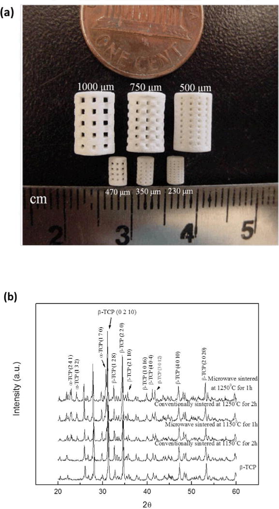
Photograph of the sintered scaffolds for mechanical strength and in vivo test (small samples) (a), and XRD patterns of the scaffolds sintered at 1150 °C and 1250 °C in conventional and microwave furnace (b).
Table 2.
Pore size (μm) and shrinkage (%) after sintering at 1250 °C by conventional and microwave sintering.
| Designed Parameters | Sintered Pore Size | Percent Shrinkage | ||||
|---|---|---|---|---|---|---|
| Sample Type | Pore size (μm) | Radial | Longitudinal | Radial | Longitudinal | |
| Conventional Sintering (CS) |
Compressive strength testing samples |
500 | 406 ± 2.12 | 421 ± 9.32 | 18.8 ± 0.87 | 15.8 ± 3.73 |
| 750 | 618 ± 9.26 | 662 ± 5.35 | 17.6 ± 2.47 | 11.7 ± 1.42 | ||
| 1000 | 816 ± 4.10 | 864 ± 4.10 | 18.4 ± 0.82 | 13.6 ± 0.82 | ||
| Microwave Sintering (MW) | 500 | 387 ± 2.34 | 401 ± 4.05 | 22.6 ± 0.94 | 19.8 ± 1.62 | |
| 750 | 548 ± 8.33 | 593 ± 16.67 | 26.9 ± 2.22 | 20.9 ± 4.43 | ||
| 1000 | 772 ± 11.57 | 804 ± 7.58 | 22.8 ± 2.31 | 19.4 ± 1.52 | ||
| In vivo samples | 230 | 130 ± 4.0 | 163 ± 5.8 | 43.4 ± 1.70 | 28.9 ± 2.50 | |
| 350 | 263 ± 1.7 | 311 ± 5.9 | 24.6 ± 0.48 | 10.9 ± 1.68 | ||
| 470 | 303 ± 3.2 | 376 ± 8.4 | 35.5 ± 0.67 | 19.9 ± 1.78 | ||
Table 3.
Designed porosity (%) and calculated total sintered open porosity (%).
| Designed Pore Size | Sintering Temperature | Sintering Method | Bulk Density (%) | Total Open Porosity (%) | Designed Porosity |
|---|---|---|---|---|---|
| 500 μm | 1150 °C | CS | 32.02 ± 2.28 | 57.87 ± 2.63 | 27% |
| MW | 38.67 ± 1.35 | 51.4 ± 3.1 | |||
| 1250 °C | CS | 37.69 ± 0.63 | 54.11 ± 3.97 | ||
| MW | 42.95 ± 1.60 | 42.75 ± 0.99 | |||
| 750 μm | 1150 °C | CS | 28.22 ± 1.19 | 63.1 ± 0.26 | 35% |
| MW | 33.95 ± 1.26 | 59.76 ± 1.42 | |||
| 1250 °C | CS | 30.80 ± 0.29 | 58.61 ± 5.35 | ||
| MW | 39.97 ± 3.83 | 46.98 ± 5.24 | |||
| 1000 μm | 1150 °C | CS | 32.91 ±0.16 | 63.83 ± 5.17 | 41% |
| MW | 35.16 ± 0.86 | 57.74 ± 4.64 | |||
| 1250 °C | CS | 26.89 ± 1.42 | 58.22 ± 0.39 | ||
| MW | 24.23 ± 1.35 | 54.27 ± 4.05 |
The constituent phases such as α- and β-TCP in sintered scaffolds were confirmed by XRD analysis. X-ray diffraction (XRD) patterns of TCP scaffolds sintered at 1150 °C and 1250 °C are compared with as-received β-TCP powder in Figure 2 (b). Major XRD peaks of scaffolds match very well with the characteristic peaks of β-TCP (JCPDS # 09-0169) and α-TCP (JCPDS # 09-0348). Additional α-TCP peaks were observed in sintered scaffolds due to high temperature β-TCP to α-TCP phase transformation (Perera et al., 2010). At a sintering temperature of 1150 °C no peaks corresponding to α-TCP were observed in conventionally sintered scaffolds, while microwave sintered scaffolds showed α-TCP peaks with lower intensities. However, both sintering methods resulted in β- to α-TCP transformation at 1250°C. Microwave sintering of β-TCP at 1150 °C for 1 h resulted in 23 % α-TCP and 77 % β-TCP, while at 1250 °C for 1 h resulted in 31% α-TCP and 69% β-TCP. Conventional sintering of β-TCP at 1250 °C for 2 h resulted in 25% α-TCP and 75% β-TCP in the sintered scaffolds. Figure 3 shows the surface morphology and microstructures of scaffolds sintered at 1250°C in conventional electric and microwave furnaces. High magnification SEM images of the scaffolds, embedded in resin and polished are presented in the inset. Microstructural images clearly show the presence of many micro pores dispersed on the scaffold walls/struts. These intrinsic and residual micro pores were measured to be ≤ 5 μm.
Figure 3.
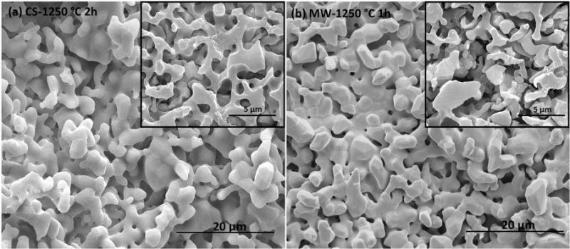
Surface morphology of scaffolds sintered at 1250 °C in conventional furnace (a), and in microwave furnace (b). SEM images (inset) of the polished surfaces embedded in a resin show the intrinsic micro porosity in the scaffold walls.
Compressive strength of sintered scaffolds is shown in Figure 4. In agreement with observed shrinkage and increased density, microwave sintering resulted in higher compressive strength at both sintering temperatures. However, no statistical difference in compressive strength was observed between conventional and microwave sintering at 1150°C for scaffolds with 500 μm designed pores. The strength of the scaffold increased with decreasing pore size or pore volume, and a maximum strength of 10.95 ± 1.28 MPa was observed for scaffolds with 500 μm pores, 27% designed porosity and 42% total open porosity, sintered at 1250°C for 1h in microwave furnace.
Figure 4.

Compressive strength comparison of the scaffolds sintered at 1150 °C (a), and 1250 °C (b) in conventional and microwave furnace (**p < 0.05, *p > 0.05, n = 10).
3.2. Cell morphology & cell proliferation
Figure 5 (a–d) shows morphologies of hFOB cells on scaffolds surfaces and pore walls after 3 days of culture. All scaffolds showed good cell adherence and cell ingrowth into the pores suggesting that the scaffolds were non-toxic. hFOB cell proliferation on these scaffolds was studied using MTT assay. Figure 5 (e) presents the cell densities observed on scaffolds with varying pore sizes as a function of culture time. After 3-day culture period, differences in cell density were observed among scaffolds with varying pore sizes. Significantly high living cell density was always observed on scaffolds with smallest designed pore size of 500 μm (Stenhamre et al. 2010). With the increasing culture time, cell density was increased on all samples. After 7 and 11-day culture periods, there was no significant difference (*p > 0.05) in cell density between scaffolds with 750 μm and 1000 μm designed pore size, although a significant difference (**p < 0.05) in cell density was observed with 500 μm pore size samples.
Figure 5.

SEM micrographs of hFOB cells showing the cell adhesion and proliferation on the scaffold surface and inside the 3D interconnected macro pores after 3 days of culture (white arrows indicate cells): 500 μm (a) & (b), and 750 μm (c) & (d); and MTT assay of hFOB on TCP scaffolds with 500 μm, 750 μm, and 1000 μm 3D interconnected macro pores after 3, 7, and 11 days (**p < 0.05, *p > 0.05, n = 3) (e).
3.3. Histomorphology
Histological evaluation was performed after 2 weeks of implantation to evaluate the new bone formation/growth into the designed pores. Table 2 also shows the designed and sintered macro pore diameter of the in vivo scaffolds. Figure 6 shows biofluid infiltration into the designed macro pores and intrinsic micro pores as well. Osteoid like new bone formation in the fibrous interzone (FIZ), and inside the 3D macro pores is observed after 2 weeks of implantation.
Figure 6.

Photomicrograph of the scaffolds showing the development of new bone formation after 2 weeks implantation in rat femur. Masson–Goldner’s trichrome staining of transverse section. OB: old bone, NB: new bone, MC: mesenchymal cell. OB: old bone, NB: osteoid like new bone.
4. Discussion
Tissue engineering scaffolds are generally porous, and the pores should be interconnected three dimensionally for successful bone defect repair (Yang et al., 2002; Will et al., 2008). 3D interconnected pores provide adequate cell penetration and vascularization for the ingrowth tissue (Bölgen et al., 2008). Interconnected macro porosity provides pathways for biofluid and facilitates ion transport, which contributes to osteogenesis (Bignon et al., 2003). Thus, scaffold fabrication with 3D interconnected porosity has attracted much attention from the scientific community. Porosity, both macro and micro, results in high surface area that helps to achieve strong mechanical interlocking between the implant and host tissue.
Conventional fabrication techniques are not very feasible to fabricate scaffolds with complex and controlled architectural designs generated using hierarchical image-based or CAD techniques (Hollister, 2005), and most SFF techniques require a lost mold or a polymer in the matrix for scaffold fabrication from CaP powder. SLS, SLA, and FDM can be used to fabricate 3D interconnected porous scaffolds from polymer powder. CaP powder can be used to fabricate ceramic scaffolds by SLS, but requires using a polymer powder mixed with CaP powder. 3DP offers direct scaffold fabrication from CaP powder using a binder solution precisely printed on each layer of the powder bed (Stevens et al., 2008). This method can also be used to make patient specific bone graft substitute.
Direct ceramic scaffold fabrication using 3DP usually suffers from sensitive depowderizing stage, i.e., removing loose powder from the interconnected pore structures (Liu et al., 2007). This is a major challenge in fabricating scaffolds with complex architecture by 3DP. This can be minimized with careful process parameters optimization. Process parameters may vary with particle size of the powder, and the type of the binder (whether the binder is aqueous or purely organic). Process parameters optimization involve, but is not limited to, adjustment of layer thickness, roller spreader speed, binder saturation, and each layer drying time. All these process parameters have been optimized for the particular β-TCP powder and the binder used in this study through a set of experiments. With careful process optimization, one can fabricate and depowderize green ceramic scaffolds for further processing.
The resulted total porosity in sintered scaffolds is between 42% and 63%, which account both the macro and micro pores present in the scaffolds. The presence of intrinsic micro pores (<5 μm) in the scaffold struts is confirmed by the SEM analysis. This resulting micro pores in the struts are due to no dense sintering, i.e., no pressure (uniaxial or isostatic) was applied at any stage of the processing to compact the samples. The most critical factor for a scaffold is to provide adequate mechanical support at the site of application. Therefore, appropriate choice of sintering method and/or cycle is important to achieve high densification, which leads to high mechanical strength in the sintered scaffolds. Densification of β-TCP at high sintering temperature is quite difficult, because β-TCP starts transforming to less dense α-TCP at 1150 °C. Bioactivity is not affected by this β to α phase transformation. Both α and β phases are bioactive and are widely used in orthopedic and dental applications (Carrodeguas and De Aza, 2011), but bioresorbability of low density α-TCP phase is higher than the high density β-TCP phase. However, this phase transformation is deleterious for mechanical properties due to spontaneous micro crack development. Micro cracks develop as a result of expansion-contraction cycle caused by the density mismatch between α- and β-TCP during phase transformation (Perera et al., 2010). Direct rapid heating of β-TCP is suggested to maximize mechanical strength by minimizing residual stress developed during phase transformation (Perera et al., 2010). Conventional sintering is more prone to micro crack and stress development due to its slow heating rate and long sintering time compared to microwave sintering.
In the present work, microwave sintering resulted in higher densification than conventional sintering at both 1150°C and 1250°C. Efficient densification by microwave sintering is achieved as a result of uniform volumetric heating allowing high heating rate and short processing time (Bose et al., 2010). The observed difference in shrinkage between radial and longitudinal direction is probably caused by the fabrication processing. 3D printing spreads the powder in X/Y plane, and this might have caused higher local green density in the X/Y plane. As a result, increased percent shrinkage is observed in the radial direction (X/Y plane) in both sintering processes. However, microwave sintering resulted in a small difference in shrinkage along different directions of the scaffolds as compared to conventional sintering as a result of uniform and effective sintering throughout the scaffold volume. Pore sizes decreased more for scaffolds sintered via microwave sintering due to higher shrinkage caused by enhanced densification compared to conventional sintering. The efficient densification and high shrinkage of microwave sintered scaffolds also contributed to their superior compressive strength compared to the conventionally sintered scaffolds. Microwave sintering at 1250 °C resulted in 46% to 69% increase in compressive strength compared to conventional sintering. A maximum compressive strength of 10.95 ± 1.28 MPa has been achieved for β-TCP scaffolds with 500 μm macro pores and 42% total volume fraction porosity when sintered in a microwave furnace at 1250 °C for 1 h. The observed decrease in the strength with increasing total volume fraction porosity is also reported by others (Kalita and Ferguson, 2006; Lin et al., 2011). Compressive strength values reported in literature for β-TCP based macro porous scaffolds fabricated by conventional and SFF techniques are compared in Table 4 with the values obtained in this study. As shown in Table 4, the maximum strength obtained in the present work is higher than those reported earlier by similar 3DP and another SFF technique, FDM (Khalyfa et al., 2007; Kalita and Ferguson, 2006). The main advantage of 3DP is that it involves only a few processing steps, and enables us to fabricate complex scaffolds architecture with ease as compared to other conventional techniques.
Table 4.
Comparison between compressive strength of macro porous TCP scaffolds obtained in the present work and earlier works (CS: Conventional sintering; MW: Microwave sintering).
| Fabrication Technique | Material | Architectural Features | Sintering | Compressive Strength (MPa) | |
|---|---|---|---|---|---|
| SFF Techniques | 3DP (Current study) | β-TCP | Porosity:~42% Pore size: 500 μm |
MW 1250 °C, 1 h |
10.95 ± 1.28 |
| Porosity:~54% Pore size: 500 μm |
CS 1250 °C, 2 h |
6.62 ± 0.67 | |||
| 3DP (Khalyfa et al., 2007) | 30 wt.% TTCP (tetracalcium phosphate) and 70 wt.% β-TCP | Porosity: ~38% Pore size: 2 mm |
CS 1400 °C, 6 h |
4.3 ± 0.3 | |
| FDM (Kalita and Ferguson, 2006) | β-TCP scaffolds with 1 wt.% MgO | Porosity: ~ 30% Pore size: ~300 μm |
CS 1250 °C, 6 h |
3.8 | |
| Conventional techniques | Combination of gel casting and polymer sponge technique (Ramay and Zhang, 2004) | HA/β-TCP biphasic calcium phosphate (BCP) | Porosity: ~73 % Pore size: ~300 – 400 μm |
CS 1144 °C, 1 h |
9.8 ± 0.3 |
| Slurry casting in pre-formed paraffin molds (Liu et al., 2010) | β-TCP | Porosity: ~80 % Pore size: ~350–500 μm Strut thickness: 140 μm |
CS 1100 °C ~ 1300 °C |
5.1 ± 1.9 | |
| Porosity: ~79 % Pore size: ~600–800 μm Strut thickness: 220 μm |
9.3 ± 2.8 | ||||
| Impregnation of β-TCP powder slurry into polymeric frames (Lin et al., 2011) | β-TCP | Porosity: ~ 65 % Pore size: ~400–550 μm |
CS 1100 °C |
10.87 ± 1.36 | |
| CS 1150 °C |
7.23 ± 0.96 | ||||
In vitro cell-material interactions reveal that the early stage cell adhesion and proliferation are favored on the rough surface of the scaffolds walls. The intrinsic micro pores on the struts improved osteoblast cell attachment and proliferation by extending cell filopedia inside the macro pores. We have observed an initial increase in cell density with the decrease in interconnected pore size by MTT assay after 3 days cell culture. The highest osteoblast cell density in scaffolds with 500 μm interconnected pores is observed at all-time points compared to scaffolds with 750 μm and 1000 μm macro pores. This is probably due to high surface area per unit volume for 500 μm pore size samples compares to 750 μm and 1000 μm samples. No significant difference in cell density is observed between 750 μm and 1000 μm after 7 and 11 days cell culture. A greater percent shrinkage is observed for in vivo samples as a result of microwave sintering compared to bigger compressive strength microwave sintered samples. This is probably due to smaller dimension of in vivo samples, as depth of penetration of microwave radiation decreases with increasing sample thickness (Clark and Foltz, 2005). Histological evaluations after 2 weeks reveal starting of osteoid like new bone formation in the fibrous interzone (FIZ) and inside the macro pores. In general, interconnected macro pores larger than 300 μm is favored for osteogenesis and vascularization (Kuboki et al., 2001; Götz et al., 2004), while minimum effective recommended pore diameter for osteogenesis is 100 μm (Hulbert et al., 1970; Holy et al., 2000; Dorozhkin, 2007). Minimum sintered pore size used in this study for in vivo osteogenesis is ~150 μm. Figure 6 shows that the sintered macro pore size 150 μm is also suitable for in vivo osteogenesis and tissue ingrowth. 3D interconnected macro pores facilitated the biofluid infiltration throughout the entire scaffold, as a result, osteoid like new bone formation can be clearly seen inside the pores. The presence of intrinsic micro pores also facilitated the osteogenesis, as they are an essential part to induce osteoinduction in a biomaterial (Habibovic and de Groot, 2007).
Conclusions
The major concern regarding porous scaffolds is their poor mechanical strength. We have applied microwave sintering to enhance the mechanical strength of 3D printed β-TCP scaffolds with 3D interconnected macro pores. The volumetric heating of microwave sintering, compared to conventional sintering, led to higher densification and hence decreased total porosity, which resulted in higher mechanical strength of these scaffolds. These β-TCP scaffolds showed excellent in vitro and in vivo biocompatibility, and osteogenesis. In vitro study revealed an increase in cell density with a decrease in pore size, and in vivo study in a rat femur model showed that both micro and macro pores facilitates osteogenesis. Our results exhibited that 3D printing of CaP scaffolds coupled with microwave sintering has strong potential for tissue engineering applications. High mechanical strength obtained by microwave sintering of this 3D macro porous ceramic scaffolds makes them suitable for variety of hard tissue repair and replacement.
Acknowledgments
The authors would like to acknowledge financial support from the National Institutes of Health, NIBIB (Grant # NIH-R01-EB-007351, Program Manager: Dr. Albert Lee), and M. J. Murdock charitable trust for funding to acquire the ExOne system. The authors also thank Valerie Lynch-Holm and Christine Davitt from Franceschi Microscopy and Imaging Center at Washington State University for their technical assistance with histology.
References
- Bandyopadhyay A, Bernard S, Xue W, Bose S. Calcium Phosphate-Based Resorbable Ceramics: Influence of MgO, ZnO, and SiO2 Dopants. J Am Ceram Soc. 2006;89:2675–2688. [Google Scholar]
- Banerjee SS, Tarafder S, Davies NM, Bandyopadhyay A, Bose S. Understanding the influence of MgO and SrO binary doping on the mechanical and biological properties of β-TCP ceramics. Acta Biomater. 2010;6:4167–4174. doi: 10.1016/j.actbio.2010.05.012. [DOI] [PubMed] [Google Scholar]
- Bignon A, Chouteau J, Chevalier J, Fantozzi G, Carret J, Chavassieux P, Boivin G, Melin M, Hartmann D. Effect of micro- and macroporosity of bone substitutes on their mechanical properties and cellular response. J Mater Sci: Mater Med. 2003;14:1089–1097. doi: 10.1023/b:jmsm.0000004006.90399.b4. [DOI] [PubMed] [Google Scholar]
- Bölgen N, Yang Y, Korkusuz P, Güzel E, El Haj AJ, Pişkin E. Three-Dimensional Ingrowth of Bone Cells Within Biodegradable Cryogel Scaffolds in Bioreactors at Different Regimes. Tissue Eng Part A. 2008;14:1743–1750. doi: 10.1089/ten.tea.2007.0277. [DOI] [PubMed] [Google Scholar]
- Bose S, Darsell J, Kintner M, Hosick H, Bandyopadhyay A. Pore size and pore volume effects on alumina and TCP ceramic scaffolds. Mater Sci Eng: C. 2003;23:479–486. [Google Scholar]
- Bose S, Dasgupta S, Tarafder S, Bandyopadhyay A. Microwave-processed nanocrystalline hydroxyapatite: Simultaneous enhancement of mechanical and biological properties. Acta Biomater. 2010;6:3782–3790. doi: 10.1016/j.actbio.2010.03.016. [DOI] [PMC free article] [PubMed] [Google Scholar]
- Butscher A, Bohner M, Hofmann S, Gauckler L, Muller R. Structural and material approaches to bone tissue engineering in powder-based three-dimensional printing. Acta Biomater. 2011;7:907–920. doi: 10.1016/j.actbio.2010.09.039. [DOI] [PubMed] [Google Scholar]
- Carrodeguas RG, De Aza S. α-Tricalcium phosphate: Synthesis, properties and biomedical applications. Acta Biomater. 2011 doi: 10.1016/j.actbio.2011.06.019. In Press. [DOI] [PubMed] [Google Scholar]
- Chanda A, Dasgupta S, Bose S, Bandyopadhyay A. Microwave sintering of calcium phosphate ceramics. Mater Sci Eng: C. 2009;29:1144–1149. [Google Scholar]
- Clark DE, Folz DC. Introduction: What is Microwave Processing? In: Folz DC, Clark DE, Folgar CE, Mahmoud MM, editors. Microwave Solutions for Ceramic Engineers. The American Ceramic Society; Westerville, OH: 2005. pp. 1–27. [Google Scholar]
- Dorozhkin SV. Calcium orthophosphates. J Mater Sci. 2007;42:1061–1095. [Google Scholar]
- Götz HE, Müller M, Emmel A, Holzwarth U, Erben RG, Stangl R. Effect of surface finish on the osseointegration of laser-treated titanium alloy implants. Biomaterials. 2004;25:4057–4064. doi: 10.1016/j.biomaterials.2003.11.002. [DOI] [PubMed] [Google Scholar]
- Groot KD. Effect of porosity and physicochemical properties on the stability, resorption, and strength of calcium phosphate ceramics. Ann NY Acad Sci. 1988;523:227–233. doi: 10.1111/j.1749-6632.1988.tb38515.x. [DOI] [PubMed] [Google Scholar]
- Habibovic P, de Groot K. Osteoinductive biomaterials—properties and relevance in bone repair. J Tissue Eng Regen Med. 2007;1:25–32. doi: 10.1002/term.5. [DOI] [PubMed] [Google Scholar]
- Hattiangadi A, Bandyopadhyay A. Strength Degradation of Nonrandom Porous Ceramic Structures under Uniaxial Compressive Loading. J Am Ceram Soc. 2004;83:2730–2736. [Google Scholar]
- Hollister SJ. Porous scaffold design for tissue engineering. Nat Mater. 2005;4:518–524. doi: 10.1038/nmat1421. [DOI] [PubMed] [Google Scholar]
- Holy CE, Shoichet MS, Davies JE. Engineering three-dimensional bone tissue in vitro using biodegradable scaffolds: Investigating initial cell-seeding density and culture period. J Biomed Mater Res Part A. 2000;51:376–382. doi: 10.1002/1097-4636(20000905)51:3<376::aid-jbm11>3.0.co;2-g. [DOI] [PubMed] [Google Scholar]
- Hulbert SF, Young FA, Mathews RS, Klawitter JJ, Talbert CD, Stelling FH. Potential of ceramic materials as permanently implantable skeletal prostheses. J Biomed Mater Res. 1970;4:433–456. doi: 10.1002/jbm.820040309. [DOI] [PubMed] [Google Scholar]
- Hutmacher DW. Scaffolds in tissue engineering bone and cartilage. Biomaterials. 2000;21:2529–2543. doi: 10.1016/s0142-9612(00)00121-6. [DOI] [PubMed] [Google Scholar]
- Kalita SJ, Ferguson M. Fabrication of 3-D Porous Mg/Zn doped Tricalcium Phosphate Bone-Scaffolds via the Fused Deposition Modelling. Am J Biochem Biotechnol. 2006;2:57–60. [Google Scholar]
- Khalyfa A, Vogt S, Weisser J, Grimm G, Rechtenbach A, Meyer W, Schnabelrauch M. Development of a new calcium phosphate powder-binder system for the 3D printing of patient specific implants. J Mater Sci: Mater Med. 2007;18:909–916. doi: 10.1007/s10856-006-0073-2. [DOI] [PubMed] [Google Scholar]
- Kuboki Y, Jin Q, Takita H. Geometry of Carriers Controlling Phenotypic Expression in BMP-Induced Osteogenesis and Chondrogenesis. J Bone Joint Surg Am. 2001;83:S105–115. [PubMed] [Google Scholar]
- Lin K, Chen L, Qu H, Lu J, Chang J. Improvement of mechanical properties of macroporous b-tricalcium phosphate bioceramic scaffolds with uniform and interconnected pore structures. Ceram Int. 2011;37:2397–2403. [Google Scholar]
- Liu C, Xia Z, Czernuszka J. Design and Development of Three-Dimensional Scaffolds for Tissue Engineering. Chem Eng Res Des. 2007;85:1051–1064. [Google Scholar]
- Liu Y, Kim JH, Young D, Kim S, Nishimoto SK, Yang Y. Novel template-casting technique for fabricating β-tricalcium phosphate scaffolds with high interconnectivity and mechanical strength and in vitro cell responses. J Biomed Mat Res Part A. 2010;92A:997–1006. doi: 10.1002/jbm.a.32443. [DOI] [PubMed] [Google Scholar]
- Pattanayak DK, Dash R, Prasad RC, Rao BT, Mohan TRR. Synthesis and sintered properties evaluation of calcium phosphate ceramics. Mater Sci Eng C. 2007;27:684–690. [Google Scholar]
- Perera FH, Martínez-Vázquez FJ, Miranda P, Ortiz AL, Pajares A. Clarifying the effect of sintering conditions on the microstructure and mechanical properties of β-tricalcium phosphate. Ceram Int. 2010;36:1929–1935. [Google Scholar]
- Ramay HRR, Zhang M. Biphasic calcium phosphate nanocomposite porous scaffolds for load-bearing bone tissue engineering. Biomaterials. 2004;25:5171–5180. doi: 10.1016/j.biomaterials.2003.12.023. [DOI] [PubMed] [Google Scholar]
- Sachlos E, Czernuszka J. Making tissue engineering scaffolds work. Eur Cells Mater. 2003;5:9–40. doi: 10.22203/ecm.v005a03. [DOI] [PubMed] [Google Scholar]
- Sachs E, Cima M, Cornie J. Three-Dimensional Printing: Rapid Tooling and Prototypes Directly from a CAD Model. CIRP Ann Manuf Techn. 1990;39:201–204. [Google Scholar]
- Sicchieri LG, Crippa GE, de Oliveira PT, Beloti MM, Rosa AL. Pore size regulates cell and tissue interactions with PLGA-CaP scaffolds used for bone engineering. J Tissue Eng Regen Med. 2011 doi: 10.1002/term.422. [DOI] [PubMed] [Google Scholar]
- Stenhamre H, Nannmark U, Lindahl A, Gatenholm P, Brittberg M. Influence of pore size on the redifferentiation potential of human articular chondrocytes in poly(urethane urea) scaffolds. J Tissue Eng Regen Med. 2010 doi: 10.1002/term.350. [DOI] [PubMed] [Google Scholar]
- Stevens B, Yang Y, Mohandas A, Stucker B, Nguyen KT. A review of materials, fabrication methods, and strategies used to enhance bone regeneration in engineered bone tissues. J Biomed Mater Res B. 2008;85B:573–582. doi: 10.1002/jbm.b.30962. [DOI] [PubMed] [Google Scholar]
- Sun W, Starly B, Darling A, Gomez C. Computer-aided tissue engineering: application to biomimetic modelling and design of tissue scaffolds. Biotechnol Appl Biochem. 2004;39:49–58. doi: 10.1042/BA20030109. [DOI] [PubMed] [Google Scholar]
- Taboas JM, Maddox RD, Krebsbach PH, Hollister SJ. Indirect solid free form fabrication of local and global porous, biomimetic and composite 3D polymer-ceramic scaffolds. Biomaterials. 2003;24:181–194. doi: 10.1016/s0142-9612(02)00276-4. [DOI] [PubMed] [Google Scholar]
- Will J, Melcher R, Treul C, Travitzky N, Kneser U, Polykandriotis E, Horch R, Greil P. Porous ceramic bone scaffolds for vascularized bone tissue regeneration. J Mater Sci: Mater Med. 2008;19:2781–2790. doi: 10.1007/s10856-007-3346-5. [DOI] [PubMed] [Google Scholar]
- Yadoji P, Peelamedu R, Agrawal D, Roy R. Microwave sintering of Ni–Zn ferrites: comparison with conventional sintering. Mater Sci Eng B. 2003;98:269–278. [Google Scholar]
- Yang S, Leong K, Du Z, Chua C. The Design of Scaffolds for Use in Tissue Engineering. Part II. Rapid Prototyping Techniques. Tissue Eng. 2002;8:1–11. doi: 10.1089/107632702753503009. [DOI] [PubMed] [Google Scholar]